Damage accidents caused by mechanical overload can be classified into the following types: damage accidents due to tensile, bending or torsion of overload, damage accidents caused by static or dynamic alternating compressive stress or shear stress, And damage caused by friction, etc.
Overloading occurs when the stress is too high or the strength is excessively reduced. Due to the influencing factors, more analysis work has certain difficulties. The following examples illustrate failures due to overload.
The passive shaft of a product is broken into four sections as shown in Figure 10-17. The spline portion of the shaft power input end is severely distorted, as shown in Figure 10-18. The outer surface of the mounting bearing is crushed as shown in Figure 10-19.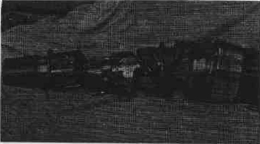
Figure 10-17 Overall view of the fracture axis
Figure 10-18 Distorted deformation of the spline part of the shaft power input end
Figure 10-19 Squeeze the outer surface of the bearing1. Chemical composition Sampling on the passive axis of the fracture, the chemical composition is shown in Table 10-9.
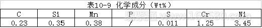
The chemical composition is consistent with the composition of 20Cr2Ni4A steel in GB3077-82.
2. Metallographic structure The microstructure of the cross-section of the shaft was observed under an optical microscope. Both the surface and the core are tempered lath martensite structures. The organization is relatively uniform. Scanning electron microscopy confirmed that the cross-sectional structure was uniform.
3. Mechanical performance test The distribution of the hardness of the test shaft in the radial direction is shown in Table 10-10.
The hardness test results show that the hardness is evenly distributed in the radial direction of the shaft, and the hardness value meets the technical requirements of the drawings. This shows that 20Cr2Ni4A steel has better hardenability.
The bearing roller hardness test results are shown in Table 10-11.
The bearing roller is qualified.
The strength index, the tensile strength of the tensile specimen taken from the axis of the fracture is as follows:
Σh=1790MPa σ,=1280MPa δ=10.8%
Toughness index αk=5.15kg·m/CM^2
4. Fracture analysis The macro photograph of the fracture is shown in Figure 10-20, Figure 10-21. The fracture shows obvious radial streaks, and the fracture of the rapid expansion zone is rough. Based on the course of the radial fringes, it is determined that the crack originates from the intersection of the oil hole and the outer surface of the shaft. As can be seen from Figure 10-21, there are two crack sources on the fracture, which are located on both sides of the oil hole. The crack is split at two points, and then spreads to the sides along the spiral surface until it finally breaks into four segments.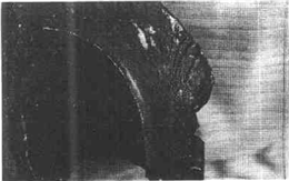
Figure 10-20 Macro photo of the fractureCareful observation of the tiny areas near the crack source revealed a small smooth zone. The fatigue fringes were observed by scanning electron microscopy as shown in Figure 10-22. The fracture at the source far from the crack is mainly dominated by the dimple type, see Figure 10-23.
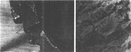
Figure 10-21 Macroscopic photo of the fracture shows the source of the crack. Figure 10-22 Fatigue stripes in the smooth region near the crack source
Figure 10-23 Dimple-type fracture in the rapid expansion zone5. Analysis Conclusion During the normal operation of the passive shaft, stress concentration is first generated at the intersection of the oil hole and the shaft to generate microcracks. Under the cyclic load, the crack gradually grows. After reaching a certain size, the crack begins to expand along the vertical direction of the maximum normal stress, forming a source of fatigue crack. The crack source has formed before the shaft fracture and gradually expands. But far from reaching the critical crack size. If it is still functioning normally, it is estimated to be a considerable period of life. From the severe plastic torsional deformation of the spline shaft, it can be judged that the bearing is subjected to a large sudden load before the crack instability propagates. According to the calculation, the minimum torque that can cause torsional deformation of the spline portion of the passive shaft power input end should be 21000 kg·m, which is 4.4 times of the design torque (4744 kg·m). Therefore, the spline portion of the input end before the fracture is plastically deformed, indicating that the bearing is subjected to an abnormal sudden load. Under the sudden load, the crack spreads from both sides of the oil hole in a direction perpendicular to the maximum tensile stress, and finally forms a spiral surface fracture of about 45° with the axis. Figure 10-24 schematically depicts the direction of crack propagation and the entire fracture process when the passive shaft breaks.

Figure 10-24 Direction of crack propagation when the shaft breaksOverloading leads to passive shaft fracture is the main cause of shaft failure. The overload may be caused by an abnormal load on the passive shaft power output end, or it may be caused by the sudden suspension of the normally operating passive shaft due to the embedding and squeezing action of the broken bearing.
HTS Wire,HTS PC Wire,HTS PC Steel Wire,Prestressed HTS Wire
Shandong Xindadi Holding Group Co., Ltd , https://www.xindadipcwire.com