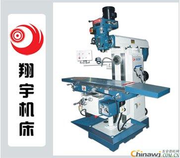
When using the milling head to connect the milling groove to the milling machine, the formula for calculating the gear ratio of the hanging wheel is:
i = z1/z2 × z3/z4 = 40P/L = 40P/(Dπcotβ)
Here, i represents the gear ratio between the indexing head spindle and the longitudinal feed screw of the table;
z1 and z3 are the number of teeth on the driving gears;
z2 and z4 are the number of teeth on the driven gears;
40 is the number of divisions;
P is the pitch of the workpiece, which is 6mm;
L is the lead of the workpiece;
D is the outer diameter of the workpiece;
β is the helix angle of the spiral groove.
For example, when milling a small lead spiral groove on an X5032 vertical milling machine with a lead L = 9mm, the calculation becomes:
i = z1/z2 × z3/z4 = 40P/L = (40×6)/9 = 26.6667
However, in practice, there is no set of hanging gears that can achieve this exact ratio. According to the hanging gear table, the maximum and minimum ratios are 14.4000 and 0.06944, respectively. This means the allowable lead range is between 16.67mm and 3456.00mm. Since L = 9mm falls outside this range, it cannot be processed directly.
To solve this issue, a double indexing head system can be used. A second indexing head is installed between the first indexing head and the longitudinal feed screw of the milling machine. The output shaft of the first indexing head is connected to the input shaft of the second indexing head via a Z/Zb gear. The second indexing head then acts as a speed-increasing device, providing a gear ratio of 40. The first indexing head is used for clamping and indexing the workpiece.
During operation, the indexing handle of the first indexing head must be manually rotated to move the milling table longitudinally. Motorized feeding is not allowed, as it could damage the worm gear pair in the second indexing head.
After this modification, the new formula for the hanging wheel ratio becomes:
Ii = z1/z2 × z3/z4 = P/L × Za/Zb = P/(Dπcotβ) × Za/Zb
Typically, when processing standard leads, Za:Zb = 1:1, so:
I = z1/z2 × z3/z4 = 6/L = 6/(Dπcotβ)
For small lead applications, the gear ratio is adjusted to Za:Zb = 1:2, resulting in:
Ii = z1/z2 × z3/z4 = 3/L = 3/(Dπcotβ)
This calculated ratio can then be used to select the appropriate gear combination from the hanging gear table.
Let's now calculate the gear ratio for the small lead workpiece mentioned earlier.
Solution: According to the formula, the required gear ratio is:
i = z1/z2 × z3/z4 = 6/L = 6/9 = 0.6667
Checking the hanging gear table, a suitable combination could be:
z1/z2 × z3/z4 = 100/90 × 60/100
Related products: X5032 vertical milling machine http://ShengJiangTaiXiChuang/244-1.html

wall lights indoor,living room floor lamps,string lights indoor,led strip lights for bedroom
HSONG LIGHTING CO,. LTD , https://www.hsonglighting.com