This is an article from the front line of production. The content of the article is not very advanced but very practical. The author analyzes the shortcomings of traditional processing methods of space cams and manual programming on CNC machine tools. Based on this, the whole process of machining space cams with MasterCAM software is explained in detail.
Xuchang Tobacco Machinery Co., Ltd. uses a variety of cam mechanisms in the hood equipment, both flat cam mechanism and space cam mechanism. Among them, the processing of key parts space cam in the space cam mechanism has always been a difficult point of machining. The conventional method adopts the index head milling or the mold-by-mold processing, and the processing is difficult, the cycle is long, the processing precision is low, and the technical level of the operator is high. Therefore, most of the space cam parts need external processing. Since we purchased CNC machine tools in the 1990s, we have replaced the traditional machining methods with CNC milling machines equipped with CNC indexing heads, which greatly improved the machining accuracy and efficiency of the cams. However, the space cams The CNC machining program has been manually programmed, and the manual programming process has many shortcomings, mainly in the following three aspects:(1) complicated programming and large workload
In the working diagram of the space cam, the theoretical or working contour size of the cam is given in Cartesian coordinates on the developed view of its outer cylinder, or given in the list. If the contour size of the cam is divided equally at 360° by 1° (which is generally the case), 360 coordinate points are input in the program, which is large in workload and error-prone. However, sometimes the contour coordinates of the cam on the drawing are given in every 10°. Because the interval is too large, the data cannot be used directly. It is necessary for the programmer to interpolate the cam contour. This is very difficult in manual programming, even impossible.
(2) Inconvenient program modification
After the program is programmed, if an error occurs during the trial cutting of the workpiece or needs to be changed, such as down milling to up milling, the program needs to be re-adjusted, and the adjustment process is very cumbersome.
(3) Cam contour processing accuracy is low
In manual programming, the two coordinate points in the program are connected by straight lines, that is, the linear interpolation method. Due to the limitation of the manual programming method, enough coordinate points cannot be obtained, so that the working contour of the processed space cam is The actual contour has a certain deviation, the surface is ribbed, not smooth, and the precision is low.
For the traditional processing and the lack of manual programming, we make full use of CAD/CAM software to solve the problem of space cam processing. Below, I will explain how to use the MasterCAM software to process space cams with a concrete example. The cam working diagram is shown in Fig. 1, wherein the relationship between the Φ20 roller center trajectory H and the rotation angle α is given by a list, as shown in Table 1.
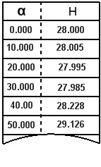
Table 1 Relationship between rotation angle α and lift H
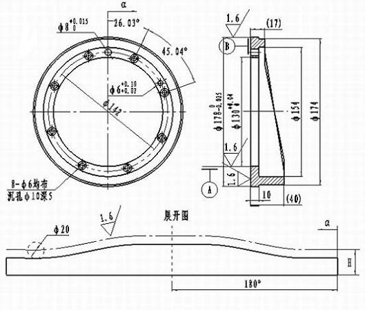
Figure 1 cam working diagram
First, the space cam processing process
1. Establish a processing model
Click the desktop icon to launch the MasterCAM software. Calculate the circumference of the cam outer cylinder L = π * D = π * 174 ≈ 546.637, draw a vertical line according to the circumference L, as shown in Figure 2. The straight line 36 is equally divided, and for each of the equal points, the H values ​​in Table 1 are sequentially input to obtain 37 contour points, as shown in FIG. Using the Spline command provided in the software, click on the 37 points obtained above to obtain the theoretical outline of the cam. Click the icon in the auxiliary menu area of ​​the software, create layer 2 in the pop-up dialog box, set the parameters as shown in Figure 4 in the pop-up dialog box, then select the theoretical profile of the cam to offset the contour line to the right. A roller radius of 10mm, after hiding other layers, get the working contour of the cam, which is the processing model we need, as shown in Figure 5.
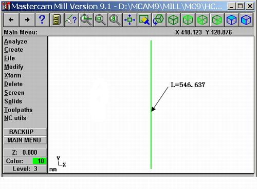
Figure 2 shows the circumference of the cam outer contour
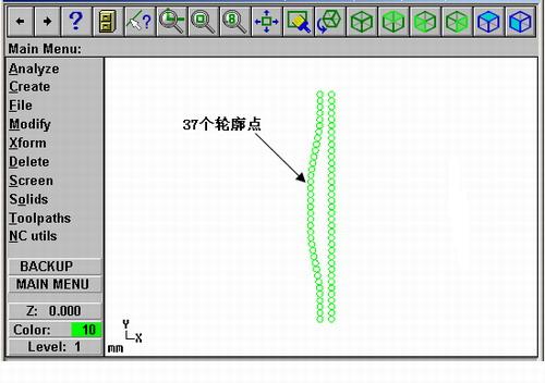
Figure 3 cam contour point
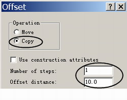
Figure 4 Offset command parameter settings
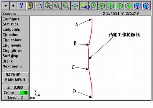
Figure 5 cam working outline
This is an article from the front line of production. The content of the article is not very advanced but very practical. The author analyzes the shortcomings of traditional processing methods of space cams and manual programming on CNC machine tools. Based on this, the whole process of machining space cams with MasterCAM software is explained in detail.
Xuchang Tobacco Machinery Co., Ltd. uses a variety of cam mechanisms in the hood equipment, both flat cam mechanism and space cam mechanism. Among them, the processing of key parts space cam in the space cam mechanism has always been a difficult point of machining. The conventional method adopts the index head milling or the mold-by-mold processing, and the processing is difficult, the cycle is long, the processing precision is low, and the technical level of the operator is high. Therefore, most of the space cam parts need external processing. Since we purchased CNC machine tools in the 1990s, we have replaced the traditional machining methods with CNC milling machines equipped with CNC indexing heads, which greatly improved the machining accuracy and efficiency of the cams. However, the space cams The CNC machining program has been manually programmed, and the manual programming process has many shortcomings, mainly in the following three aspects:
(1) complicated programming and large workload
In the working diagram of the space cam, the theoretical or working contour size of the cam is given in Cartesian coordinates on the developed view of its outer cylinder, or given in the list. If the contour size of the cam is divided equally at 360° by 1° (which is generally the case), 360 coordinate points are input in the program, which is large in workload and error-prone. However, sometimes the contour coordinates of the cam on the drawing are given in every 10°. Because the interval is too large, the data cannot be used directly. It is necessary for the programmer to interpolate the cam contour. This is very difficult in manual programming, even impossible.
(2) Inconvenient program modification
After the program is programmed, if an error occurs during the trial cutting of the workpiece or needs to be changed, such as down milling to up milling, the program needs to be re-adjusted, and the adjustment process is very cumbersome.
(3) Cam contour processing accuracy is low
In manual programming, the two coordinate points in the program are connected by straight lines, that is, the linear interpolation method. Due to the limitation of the manual programming method, enough coordinate points cannot be obtained, so that the working contour of the processed space cam is The actual contour has a certain deviation, the surface is ribbed, not smooth, and the precision is low.
For the traditional processing and the lack of manual programming, we make full use of CAD/CAM software to solve the problem of space cam processing. Below, I will explain how to use the MasterCAM software to process space cams with a concrete example. The cam working diagram is shown in Fig. 1, wherein the relationship between the Φ20 roller center trajectory H and the rotation angle α is given by a list, as shown in Table 1.
Table 1 Relationship between rotation angle α and lift H
Figure 1 cam working diagram
First, the space cam processing process
1. Establish a processing model
Click the desktop icon to launch the MasterCAM software. Calculate the circumference of the cam outer cylinder L = π * D = π * 174 ≈ 546.637, draw a vertical line according to the circumference L, as shown in Figure 2. The straight line 36 is equally divided, and for each of the equal points, the H values ​​in Table 1 are sequentially input to obtain 37 contour points, as shown in FIG. Using the Spline command provided in the software, click on the 37 points obtained above to obtain the theoretical outline of the cam. Click the icon in the auxiliary menu area of ​​the software, create layer 2 in the pop-up dialog box, set the parameters as shown in Figure 4 in the pop-up dialog box, then select the theoretical profile of the cam to offset the contour line to the right. A roller radius of 10mm, after hiding other layers, get the working contour of the cam, which is the processing model we need, as shown in Figure 5.
Figure 2 shows the circumference of the cam outer contour
Figure 3 cam contour point
Figure 4 Offset command parameter settings
Figure 5 cam working outline
3. Establish a finishing tool path
Click the icon button in the software, the system prompts to select the series connection, select the A-D cam contour line in Figure 5 as the processing object, and then click the main menu area to pop up the contour processing operation setting dialog box, where the tool parameter page is set and thick. The same processing, in order to make the allowance even during finishing, arrange the semi-finishing tool sequence before finishing. To do this, set the Linerization tolerance value to 0.025 and the XY stock to leave value to 0.1 to generate the tool path in the contour parameter page. Set the upper two values ​​to 0.0005 and 0 respectively to generate the finishing tool path. Click on the pop-up action manager and the two actions you just created are displayed in the manager, as shown in Figure 12. Click the and button in the operation manager to generate the finished tool path and solid simulation effect diagram, as shown in Figure 13 and Figure 14. Click the button in the operation manager, select the FANUC post-processing program, and generate the machining program for CNC milling. As shown in Figure 15, the program passes the trial on the car, and the processed cam working surface is very smooth, fully meeting the drawing requirements. The space cam machining problem was solved satisfactorily.
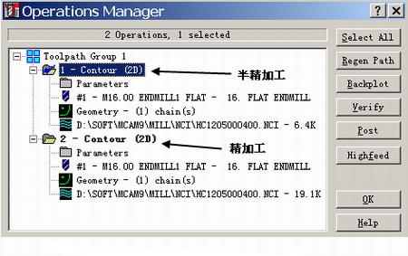
Figure 12 establishes semi-finishing and finishing operations
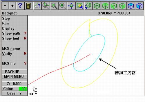
Figure 13 Finishing tool path

Figure 14 Finishing tool path renderings
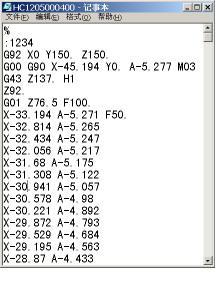
Figure 15 cam machining program
Second, the conclusion
The solution to the problem of space cam machining fully embodies the important role of CAD/CAM software in CNC machining. With MasterCAM software, we have solved a number of complex space cam and planar cam machining problems. At present, there is no difficulty in processing cam parts in the workshop, and we are gradually expanding the application range of software programming technology and achieving very good results. Therefore, the personnel engaged in CNC machining can only deeply understand the processing potential of CNC machine tools and continuously improve the process capability of the machine shop, only by deeply understanding and mastering one or more CAD/CAM processing software and using them in practice. Improve the quality of the product.
CPF series ClO2 generator is a kind of positive pressure disinfecting system. It is adopted Positive Pressure dosing technology for the first time in the world. It can brought disinfectant solution directly to the pressured water with simple, safe, reliable, stable operation and other characteristics. Technology: Use sodium chlorite and hydrochloric acid as raw materials, transmission of raw materials through two metering pumps to the reactor, produce the concentration of more than 95% of high-purity chlorine dioxide solution added to water for disinfection. It can automatically adjust the dosage of clo2 solution through flow control and residual chlorine display system. When lack of raw materials, the liquid level alarm system will give audible and visible alarm signals and automatically cut off the power supply of equipment. The entire control system use PLC as the core, on-site parameters setting through the touch screen and remote control through the computer, to realize high-performance automated management of Disinfection System. Raw materials conversion rate is more than 95%.
*Related Products:industrial clo2 generator ,Chlorine Dioxide Generator,chlorine dioxide production system,patent chlorine dioxide generator,chlorine dioxide production.
Chlorine Dioxide Generator
Chlorine Dioxide Generator, Chlorine Dioxide Disinfection, Automatic Chlorine Dioxide Generator
Nanjing Ligong Shuifu Environmental Protection Technology Co.,Ltd. , http://www.watermanclo2.com