1 Introduction
Foundry is one of the important industrial ministries of the national economy, reflecting the scale and level of manufacturing industry in a country. With the vigorous development of aviation, aerospace, shipbuilding, automobile, machinery and other industries, the demand for large and complex castings is increasing, and the requirements for the properties of cast metal and the reliability of castings are becoming higher and higher. The development of advanced manufacturing technology requires the development of castings to be lighter, more precise, tougher, composite and environmentally friendly.
The rapid development of CAD/CAE technology and its wide application in foundry production can be achieved by numerical simulation and simulation of the manufacturing process. This work uses numerical calculation as the basic method to simulate the flow field, temperature field, stress field and microstructure of the casting process, thus helping the process designer to analyze the metal flow state, solidification process temperature distribution and stress distribution at different times. The important physical parameters such as crystal grain size and morphology are known, and based on this, it is predicted whether there are defects such as shrinkage, porosity, inclusion, segregation and hot crack, which can realize the design of casting process - check - Redesign - optimize the entire process of design to improve casting quality, shorten trial production cycle, reduce production costs, and improve market competitiveness. At the same time, using computer and other high-tech to transform and manufacture traditional industries is the common trend of science and technology development at home and abroad. It is the frontier of the discipline in the field of casting, and it is also an important way for the casting process to move from “experience design†to “scientific guidanceâ€. significance.
2 CAD practical application
2.1 Collection, processing and digitization of product technical information
Create a model and product technical information base of a diesel engine body (see Figure 1). First, collect and process the technical information of the product, and digitize the technical information. For example, where the design basis and reference datum of each part of the product are, this is where It is the basis of the future processing reference and assembly benchmark; after that, the geometrical features and interdependence of each part of the structure are analyzed. These are the basic elements that constitute the design product, and the size, shape and position of the space are essential; Acquisition of related design intents such as material setting and unit setting.

Figure 1 Modeling of a fuselage casting
2.2 Process design
After correctly understanding the design drawing intentions, the product model is established, the process information base is established, the casting system of the casting, the riser, the riser sleeve, the inner and outer cold iron are designed, and the process system is modeled (see Figure 2).
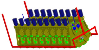
Figure 2 Modeling of a fuselage process system
A fuselage casting system model (see Figure 3): the foot plate faces up and the cylinder hole faces down. The size of the gate pocket is φ120 xφ100 x 90; the size of the sprue is φ90; the cross section of the runner is 80 x 70/R8 x 60; the section size of the gate is φ28; see the figure below.

Figure 3 Modeling of a body casting system
A cold iron model of a fuselage casting (see Figure 4): 62 types of cold iron are used, totaling 886 pieces, as shown in the figure below.
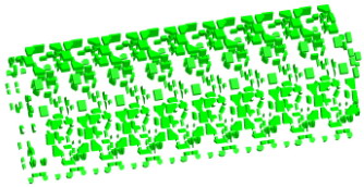
Figure 4 Modeling of a cold iron in a fuselage
The riser model of a fuselage casting (see Figure 5): There are 18 risers in the two rows of the bottom plate, the size of each riser is φ195 x 325, the size of the riser neck is 80 x 60 x 40; the cylinder face has nine Group risers, the size of the spherical riser of each group is the same as SR95; see the figure below.
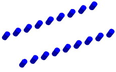
Figure 5 Modeling of a fuselage riser
A fuselage casting riser sleeve model (see Figure 6): a total of 18 rows of two, each riser sleeve size is h = 360mm, wall thickness δ = 28mm; see the following figure.

Figure 6 Modeling of a fuselage riser
Steel Pipe for a fuselage casting (see Figure 7): a section of the central oil pipe, the size is φ152 (outer circle) xφ100 (inner hole) x 6350, δ=5mm; a small section of the left and right sides of the rear end of the fuselage, circular section size It is φ60 (outer circle) xφ50 (inner hole), δ=6mm; see the figure below for details.

Figure 7 Modeling of a fuselage casting
At the same time, the process parameters such as the machining allowance and draft angle of the casting are considered in the modeling. After all of these process design modeling is completed, the meshing of the model can be performed to provide an original basis for the thermal flow analysis pre-processing of large complex castings.
2.3 3D modeling, numerical simulation and process optimization
After the three-dimensional model of large complex castings (airframe, cylinder head, etc.) and its three-dimensional model of internal and external cold iron were built on the computer, the filling and solidification of the castings were carried out according to the production conditions of the diesel castings using ProCast simulation software. The process performs numerical simulation and iteratively optimizes the process to establish a technical information base system for optimal casting formation (see Figure 8).

Figure 8 Product Model Technical Information Library System Diagram
2.4 Casting mold production and machining
According to the characteristic information of the model, the mold or sand core for casting is produced (see Fig. 9 and Fig. 10), and the laser product can be obtained by laser rapid prototyping technology, for example, laser rapid forming of a diesel engine cylinder head (see Fig. 11); In the process of product finishing, the NC processing program can be quickly generated according to the engineering data information to complete the final processing of the product; finally, the data management (PDM) of the product can be carried out according to the above engineering technical information, and online detection, quality evaluation and Integrated management of production activities such as assembly and commissioning.

Figure 9 Laser rapid prototyping of a cylinder head air passage Figure 10 Laser rapid prototyping of a cylinder head water channel
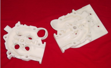
Figure 11 Laser rapid prototyping of a cylinder head
2.5 Production process tracking and improvement
Using the established technical information library of all products, the process from design, process to manufacturing and performance comparison analysis will be tracked and reproduced on site, and problems will be promptly corrected and improved. In this way, the whole process of the above production can be predicted in advance, unnecessary waste is reduced, the production chain of the product is shortened, and the production process is more automated and humanized.
Creating a three-dimensional parametric part model of large complex castings and forgings is not only for modeling, but the correct model should be the original original technical information base, which can be applied to forming process analysis, structural optimization analysis, manufacturing, measurement analysis, production management. Throughout the process, design modification and adjustment, CAE analysis, assembly, mechanical analysis, motion analysis, CNC machining, etc. are made easy, because data and parameter driving are possible based on a technical information database. It can be said that the near-term goal of modeling is to modify. This requires that the product model created is complete in structure, complete in size and geometric constraints, so that in the process of product design, processing and analysis, the unreasonable structure can be adjusted at any time to ensure consistency.
3 CAE production practical application
In recent years, the functions of casting CAE commercialization software have gradually increased, including ProCAST in the United States, MAGMASOFT in Germany, CastCAE in Finland, Simulor in France, Forcast in Spain, and Soldia and Castem in Japan. From the functional point of view, many softwares are mostly based on the finite difference method, which can simulate the temperature field and flow field of sand casting, metal casting, precision casting, pressure casting, etc., and can predict the shrinkage and shrinkage of castings. Pine and other defects, but the simulation of the stress field and the prediction of cracks appear to be incapable.
ProCAST software is a finite element method (FEM) based casting process simulation software developed by ESI [5], which can perform three-field coupling simulation of flow field, temperature field and stress field. ProCAST uses a numerical method based on finite element method (FEM). Compared with finite difference method (FDM), finite element method has great flexibility, especially suitable for simulating various physical phenomena in complex casting molding process. ProCAST provides the ability to consider the effects of gas, filtration, high pressure, and rotation on the filling of castings. It can simulate the filling process of almost all casting processes such as low pressure casting, pressure casting, centrifugal casting, etc. In terms of stress analysis, by using elastoplasticity And the viscoplastic and unique method of dealing with the thermal and mechanical contact interface of the casting/casting, which has the ability to analyze the stress and deformation of the casting. Through analysis, various phenomena of the casting process, formation and distribution of casting defects, and simulation and prediction of the final quality of the casting can be obtained. Figure 12 shows the entire process of casting process optimization. Figure 13 shows the steps of the ProCAST software for simulation analysis.

Figure 12 Casting process optimization flow chart Figure 13 ProCAST analysis process
Introduce CAE in the design process to guide design decisions, simulate the flow field, temperature field, stress field and microstructure in the casting process (see Figure 14) by numerical simulation and simulation of the large complex casting manufacturing process. Help process designers to understand important physical parameters such as metal flow state, solidification process temperature distribution, stress distribution, crystal grain size and shape at different times, and based on this, predict whether there are shrinkage holes, looseness, inclusions, Defects such as segregation and hot cracks can be realized, and the casting process design—checking—redesigning—can optimize the whole process of design, ultimately improve the quality of castings, shorten the trial production cycle, reduce production costs, and improve product competitiveness.
3.1 Casting filling simulation
The casting filling process plays a decisive role in the final quality of the casting. Many casting defects, such as insufficient pouring, cold insulation, gas filling, oxidizing slag, even shrinkage and shrinkage, are closely related to the filling process of the casting. ProCAST software can accurately express the filling process and defect generation process, which is of great significance for optimizing the filling system design and avoiding casting defects caused by unreasonable filling.
In order to test the accuracy of ProCAST software in flow field prediction, we selected the benchmark test of pure aluminum filling by J. Campbell of Birmingham, England to verify the accuracy of the software.
The X-ray filling results of the test results are shown on the left. The right picture shows the simulation of the ProCAST software. It can be seen from the figure that the ProCAST software can accurately simulate the filling process of the entire casting, which is a good predictor of the casting system. Gas defect.
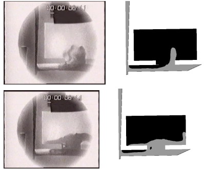
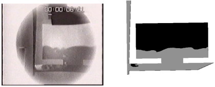
Figure 15 Comparison of actual casting and ProCAST software simulation results
In the casting process design of impeller castings, we applied ProCAST software to predict the unreasonable design of the impeller casting casting system, and proposed the process improvement to make the casting a successful casting.
In the original design process, the flow distribution of the inner gate of the impeller is extremely unreasonable. After the improvement, the filling of the casting is relatively uniform, and the flow distribution of each ingate is relatively uniform.
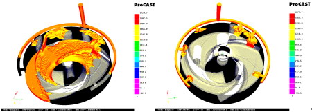
Figure 16 Comparison of the pouring system before and after improvement
3.2 Casting solidification simulation
Most of the defects in the casting process are mainly shrinkage and shrinkage defects, and these defects are mostly formed during the solidification process of the casting. Therefore, it is extremely important to accurately predict the solidification process of the casting, and to predict the shrinkage and shrinkage defects. ProCAST software can accurately predict the shrinkage and shrinkage defects of castings. The software provides a variety of prediction methods for shrinkage and shrinkage defects based on unstable heat transfer calculation. Commonly used are: temperature gradient method, solid phase rate gradient method, The solidification time gradient method, the Niyama criterion method and its variants, and the density-related criteria of the ProCAST software. Engineers can achieve the purpose of predicting shrinkage and shrinkage defects through a combination of multiple criteria.
When we optimized a steel casting, we applied a variety of criteria. After several simulations, we finally solved the shrinkage and shrinkage of the castings in production.
The initial casting process was simulated and analyzed. The temperature gradient method and the solid phase rate gradient method were used to show no defects. The ProCAST software's own criteria showed that there were shrinkage and shrinkage defects at two locations, which is consistent with the actual casting flaw detection results. After many optimizations, the problem was finally solved, and the castings produced were dense and defect-free.
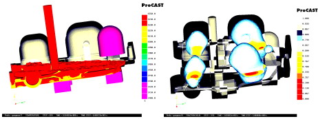
Fig.17 Casting piece inclined pouring temperature fieldFig.18 Casting solid phase fraction distribution map
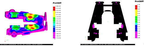
Fig.19 Distribution of solidification time of castingsFig.20 Distribution of shrinkage and shrinkage of castings
3.3 Casting stress field simulation
In casting production, thermal cracking often occurs due to structural reasons of the casting and improper processing, or there is a large residual stress or residual deformation in some parts, which is common in steel castings, especially large steel castings. These defects seriously affect the quality and service life of the castings, and these two defects are directly related to the generation and development of thermal stress during the solidification process. Iron is a thermal cracking defect, which is generally produced in the quasi-solid phase region, and With the subsequent cooling of the casting, the cracks continue to expand, often causing the casting to be scrapped.
When we produce a steel casting with 35CrMo material, cracks often appear near the inner gate and often extend into the interior of the casting, which seriously affects the normal development of the subsequent work. The workshop technician has added a convex near the inner gate. The subsidy was reduced to reduce the crack to the casting, but the problem was not completely solved. Later, the ProCAST software was used to simulate the stress field of the casting. According to the simulation, improvement measures were proposed to completely eliminate the crack defects in the casting.
4 Conclusion
The CAD/CAE application analysis of a large complex casting such as a diesel engine fuselage and cylinder head of a ship adopts a combination of theoretical analysis, software simulation verification and experimentation, and has developed a practical research direction to carry out large-scale complex product models and The optimization research of the technical information base accelerates the process of CAE simulation analysis and solves the problems in production.
Stainless Steel Foil 304L & 316L
Thick Strip,Stainless Steel Foil,Cold Rolled Steel Foil
Ningbo Qiyi Precision Metals Co., Ltd. , http://www.qiyi-metal.com