From a macroscopic point of view, there is no obvious plastic deformation near the fatigue fracture, which is a brittle fracture. The typical fatigue fracture can be clearly divided into three regions with different morphological features, namely fatigue core zone, fatigue crack growth zone and instantaneous breaking zone, which represent different processes of fatigue failure. Figure 6-1 is a typical fatigue fracture. The characteristics of the three regions are discussed separately below.
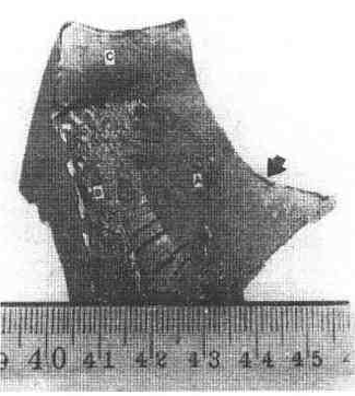
Figure 6-1 Typical fatigue fracture
In the figure, the arrow indicates the crack source, the A area is the fatigue crack extension area, the B area is the instantaneous break zone, and the C area is the shear lip.
First, the fatigue core (or fatigue source)
The position can be roughly judged with the naked eye or with a low magnification magnifying glass, which is the starting point for fatigue damage. On the fatigue fracture, it is a small, smooth, fan-shaped area. In fact, the real source of fatigue is the crack initiation and microcracking (tens of microns long) extensions located roughly at the "fan" shank, and its formation process will be analyzed in detail in the mechanism study. Most of the bright areas are formed when the crack length is less than 1mm, and the cracks are slowly extended. In this stage, the crack opening displacement is small and the expansion is slow. Repeated opening and closing cause the fracture surfaces to be squeezed on each other to form the most fracture. Smooth area. In this area, it is also common to see that the bead lines centered on the fatigue core are emitted outwards, and some can also see radiation steps or line marks radiating to the surroundings, and can extend to far places, which indicates that fatigue cracks are not simple. A macroscopic plane, but extending along a series of macroscopic flats with height differences, is often a jagged microcrack, or there are several sources of fatigue in the core.
The fatigue core is always formed at the surface, but if there are defects inside the component, such as brittle inclusions, voids, segregation of chemical components, or treatment with some kind of table, it may also be produced "under the skin" or internally. There are sometimes more than one fatigue core, there may be two or more, especially low cycle fatigue, and the fracture often has several fatigue cores at different locations.
Second, fatigue crack growth zone
This is the most important feature area on the fatigue fracture, and in many cases it occupies most of the fracture. In this area, the surface is rougher and darker than the fatigue core area, and it is often seen to have stripes of bellows, clam shells or beach corrugations. These stripes are centered around the crack core and spread around to form a cluster of curved lines that are perpendicular to the crack propagation direction. After the crack is formed, when the tensile stress is applied, the crack is opened, the tip is passivated, closed when pressed or unloaded, the crack tip is re-sharpened, and the cycle is pulled again. Due to the stress concentration at the tip, subcritical expansion occurs, leaving A fatigue glow, these brilliance is difficult to distinguish. The visible bead lines are mostly caused by the fluctuation of the load spectrum. The start and stop of the machine, or the stress fluctuation caused by accidental factors during the operation will cause the bead line to be generated. When the constant stress or constant strain test is carried out in the laboratory, the load spectrum is relatively stable, and the fracture generally does not have this feature. At this time, the surface of the fatigue fracture surface is rubbed due to repeated compression, so that the area becomes smooth and fine-grained. Sometimes it even looks like a porcelain structure. For low cycle fatigue, this bead line is also not observed.
The step developed by the fatigue core zone, the more the step is developed in the expansion zone, becomes a strip of radiation strips emitted by the crack source, which are perpendicular to the bayline.
Third, the instantaneous break zone
This is the region formed by the instability and expansion of the fatigue crack to the critical dimension. Its characteristics are similar to those of the rapidly breaking radiation zone and shear lip in the static tensile fracture, the presence or absence of the radiation zone and the shear lip, and the size and The characteristics of the material and the history of the load are related. When the load is large or there is sudden overload, the two features are obvious, and the proportion of the fracture is also large. If the load is stable, the fracture zone may not see obvious radiation zone, but only the shear. Cut the lip, the instantaneous break zone is also small. However, for some brittle materials, the instantaneous break zone is characterized by a crystalline brittle fracture.
According to the characteristics of the load, fatigue fracture can be divided into bending fatigue, axial (pull-pull, pull-pressure or pulsation) fatigue fracture, torsional fatigue fracture and composite fatigue fracture, among which bending fatigue fracture is the most common, pure shaft It is less common to fatigue fractures. The macroscopic features of these fractures are now discussed separately.
1. Fatigue fracture
Because of the fatigue load, the maximum normal stress always appears at the surface, so the common feature of the bending fatigue fracture is that most of the fatigue core is formed on the surface, and then expands in the direction perpendicular to the maximum normal stress, and the crack reaches the critical point. After the size, the member breaks quickly. However, the bending fatigue load varies with time, and the corresponding deformation and fatigue fracture mechanisms also have their own characteristics, which can be summarized as one-way bending fatigue, two-way bending fatigue and rotational bending fatigue. Take the circular section shaft parts as an example, and introduce them as follows.
(1) One-way bending fatigue
The force and deformation characteristics of uniaxial bending fatigue are shown in Figure 6-2. The normal stress on the section is linearly distributed along the height of the section. The maximum tensile stress and compressive stress are respectively at points A and B, and they are only According to the unidirectional stress, the tensile stress at point A changes with time as shown in Figure 6-2c. Fatigue sources are stored here. If there is no stress concentration, the velocity of crack propagation from the core to the periphery is basically the same, forming a bead line as shown in Figure 6-2(a), and finally breaking off on the opposite side of the fatigue core. If there are stress concentration conditions, such as the stepped part of the shaft part, the stress concentration is large due to the root of the step, and the fatigue crack spreads rapidly on both sides near the surface, forming a fracture shape as shown in Fig. 6-2(b). The area of ​​the instantaneous breaking zone is larger than that of the non-stress concentration phenomenon.
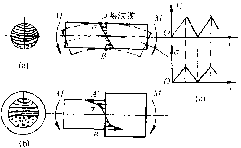
Figure 6-2 Schematic diagram of uniaxial bending fatigue stress and fracture
(2) Two-way bending fatigue fracture
The fatigue load (bending moment) and deformation of the biaxial bending fatigue are shown in Figure 6-3. Under the action of the biaxial interaction, the neutral axis is bounded, and the upper and lower parts of the component are respectively subjected to tension and compression. The effect of two-way alternating stress occurs at the surface farthest from the neutral axis.
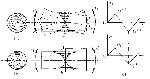
Figure 6-3 Schematic diagram of the force and fracture of biaxial bending fatigue
If M+=M-, the maximum normal stress at the farthest point on both sides of the neutral crucible is equal, and the fatigue source is usually generated simultaneously on the surfaces of the two sides, and simultaneously expands inward, and the expansion depth is also substantially equal. If there is stress concentration, the fracture shape is shown in Figure 6-3(b). The front edges of both cracks are convex and the instantaneous break zone is larger.
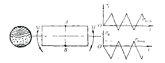
Figure 6-4 Schematic diagram of stress changes on the upper and lower sides of M+≠M- bidirectional bending
If M+≠M-, the maximum stress equivalent at the farthest point on both sides of the neutral axis is reversed, as shown in Figure 6-4. For example, the maximum tensile stress at point A is equivalent to the large compressive stress at point B, and the maximum tensile stress at point B is lower than the maximum tensile stress at point A. At this point, a fatigue source is first generated at point A, and then a second source of fatigue (related to the M+/M- ratio) may be generated at point B, and the former expands faster.
In addition, if the fatigue load is low, it is difficult to form a fatigue source. Surface quality and material defects may play a more important role in the formation of fatigue sources. The fatigue source will appear at the surface of surface defects such as surface scratches and inclusions. The fatigue source is formed on the opposite side, and the depth of expansion of the two fatigue cracks is also different. As a result, the resulting fracture is asymmetrical.
(3) Rotating bending fatigue fracture
Typical stresses and deformations of rotational bending fatigue are shown in Figure 6-5. The tensile stress and compressive stress of each point on the member subjected to the sinusoidal continuous alternating action have the largest stress amplitude at each point on the surface. Therefore, all points on the equal bending moment section have the same chance of fatigue source initiation. However, if the load is small, a crack source is often generated at one place. And expand to both sides and inside. Due to the rotation of the member, the tensile stress is larger than the internal stress alternately on both sides of the fatigue source. The fatigue crack spreads faster on both sides than the center portion, and the formed bead line is flat. The rotation of the member corresponds to the action of the bending load in the opposite direction of rotation, so that the leading edge of the fatigue crack expands rapidly in the direction of the load movement, and the expansion speed in the reverse load movement direction is slow. Therefore, the instantaneous break zone of the rotary fatigue fracture is not directly opposite the fatigue source, but is programmed to an angle, usually up to 15° or even larger. The direction of this offset is opposite to the direction of rotation of the member, and the direction of rotation of the member can be inferred from the relative position of the fatigue core and the instantaneous break zone.
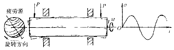
Figure 6-5 Schematic diagram of the force and deformation of the rotating bending fatigue

Figure 6-6 Schematic diagram of the rotational bending fracture and the final deflection zone position deflection
Stress concentration can significantly affect the fracture morphology. For shaft members with circumferential notches or steps, when the stress concentration is not large, only one source of fatigue may be generated, and the instantaneous break zone is on the corresponding side of the fatigue source. Figure 6-6 shows the stress-cracking at the corner of the bottom of the keyway, which is the crack initiation point. When the stress concentration is large, it is possible to generate several fatigue sources along the periphery, which simultaneously expand to the inside, and the instantaneous break region will be inside. The greater the nominal stress, the more the fatigue source tends to increase, and the more the instantaneous fault zone moves toward the center. If the momentary zone is at the center, the number of alternating load cycles before the fracture will generally not exceed 10,000. The stress level in this case is on average 1.5 to 2.0 times the fatigue limit. When the short-cut zone is located on the outside of the shaft, it typically undergoes millions of revolutions before breaking. Therefore, depending on the position and size of the instantaneous break zone, the magnitude of the load or nominal stress on the shaft can be inferred. Figure 6-7 shows the effect of stress concentration and load on the fracture profile of rotating bending fatigue.
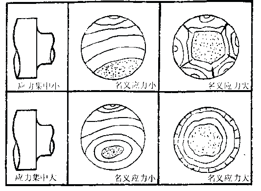
Figure 6-7 Effect of stress level and stress concentration on the shape of rotating bending fatigue fracture
If the stress is distributed evenly along the axial direction, the bending fatigue fracture is generally a flat fracture perpendicular to the axis. If the stress concentration is caused by the sudden change of the sectional area, the bending fatigue fracture formed at the stress concentration intercept is not flat. Instead, it is a dish-shaped so-called dish-shaped fracture, and Figure 6-8 shows the principal stress line and crack propagation path.

Figure 6-8 Schematic fracture and formation
If there is a constant stress concentration at the journal and at the same time a certain amount of torque is applied, the rotational bending fatigue may generate several fatigue cores at the same time. Due to the action of the torque, the cracks will expand forward in a spiral shape, and finally these cracks will meet at the center of the shaft to form a ratchet-shaped fracture.
In summary, the bending fatigue fracture morphology of the circular section shaft parts can be summarized as shown in Figure 6-9.
2. Axial fatigue fracture
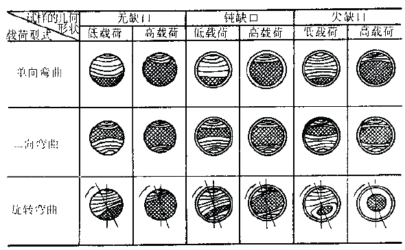
Figure 6-9 Schematic diagram of the shape and relative area of ​​the three fracture zones of the bar under different bending loads and stress concentration conditions
If the component is only subjected to the axial fatigue load, an axial fatigue fracture will occur, which is rare in engineering practice. The axial tension or tensile-compression fatigue with uniform stress distribution is generally formed on the surface. After the micro-crack is formed, the crack spreads in a direction perpendicular to the maximum tensile normal stress, that is, perpendicular to the axis. After reaching the critical dimension, it is unstable and fractured. If there are defects or large inclusions inside the component, the fatigue source may be generated in the defect or the inclusion. As shown in Figure 6-10, the fatigue fracture of the steam hammer piston rod is located in the center of the fracture, and the fatigue source is also In the center of the extension zone, the outside is a short-cut zone with a distinct radial pattern.
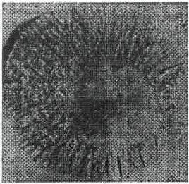
Figure 6-10 Fatigue fracture of the steam hammer piston rod
The axial fatigue fracture morphology is related to the magnitude of the load, the presence or absence of stress concentration, and the size.
(1) The effect of stress magnitude
When the working stress is lower than or exceeds the fatigue limit, it is a low stress fatigue. The biggest characteristic of the fracture is that the fatigue crack propagates sufficiently, so the fatigue zone is large, the instantaneous break zone is small, and the fatigue life is long. Bevel-like streaks due to load fluctuations often appear on actual parts, as shown in Figure 6-11(d).
(2) Influence of stress concentration
For a smooth circular axis, no stress concentration, the crack from the crack source to the direction of the expansion speed is basically the same, the crack front is convex convex arc as shown in Figure 6-11 (a, d).
If there are steps or notches on the shaft and there is stress concentration, the stress concentration on the outer side is more significant, and the crack propagation speed on both sides is faster than the middle. The crack front is corrugated (high stress) as shown in Figure 6-11 (b, c), or inwardly convex (low stress), as shown in Figure 6-11 (e, f). )
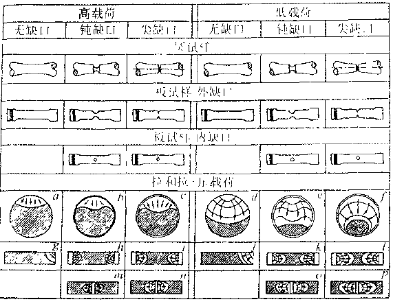
Figure 6-11 Schematic diagram of the macroscopic topography of the fatigue fractures of bars and plates under various pull-pull (pull-and-pull) cyclic loads and stress concentration factors
When the stress is high, the fatigue zone is small, the instantaneous fracture zone is large, and the fatigue life is short, as shown in Figure 6-11(a).
For the plate-shaped member, the fatigue core often appears at the corners, as shown in Fig. 6-11(g). If there are notches on both sides, the crack core expands toward the center in the notch root as shown in Fig. 6-11(h, i).
3. Reverse fatigue fracture
The shaft parts have a linearly distributed shear stress in the cross section and the longitudinal section under the action of torque, as shown in Figure 6-12. The shear stress is the largest at the outermost edge, and the core is zero. From the stress analysis, the maximum tensile stress and compressive stress are obtained on the inclined surface at 45° to the axis.
A common feature of the several forms of fatigue cracking described above is that once a crack is formed, the crack generally extends in a direction perpendicular to the maximum tensile normal stress. However, for torsional fatigue, there are two possible ways of failure. One type is positive-cut type, and the crack extends along with the maximum tensile normal stress to form a diagonal fracture at an angle of 45° to the axis. Generally brittle material It is broken in this way; one type is a cut-off type, and the crack spreads in the direction of the maximum shear stress to form a flat fracture perpendicular to the axis, and the plastic material generally breaks in this manner.
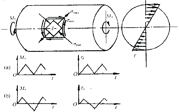
Figure 6-12 Schematic diagram of torsional fatigue stress
Figure 6-13 is a more typical two fracture photos
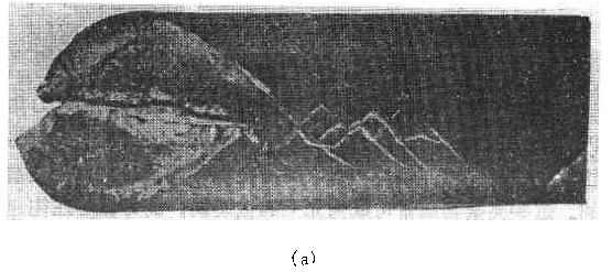
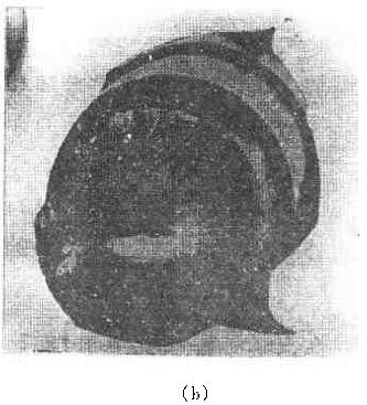
Figure 6-13 Typical torsional fatigue fracture
(a) normal type; (b) cut type
Mixed-type fractures sometimes occur, such as expansion with a cut-off type, and later a positive-to-break type expansion. Common torsional fatigue fracture patterns can be summarized into several forms as shown in Figure 6-14.
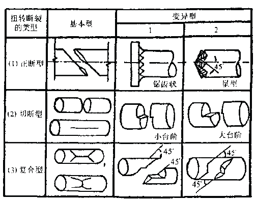
Figure 6-14 Various forms of torsional fatigue fracture
For positive torsional torsional fatigue, the fractures are mostly ratchet, serrated and star shaped.
The ratchet-shaped fracture is formed under the action of one-way pulsating torsional stress. Under the action of repeated torsional stress, a plurality of fatigue sources can be simultaneously generated at the angles, notches or some weak points of the shaft surface, and respectively expand in a direction at an angle of 45° with the axis under the action of the tensile stress. And spirally toward the center, when the crack spreads to a certain extent, the final joint portion is instantaneously broken to form a radial fracture having a ratchet pattern. The formation process is shown in Figure 6-15.


Figure 6-15 Schematic diagram of the fracture and formation of fatigue fracture
The serrated fracture is formed by a two-way alternating torsional load. After the fatigue source is formed at multiple locations, the cracks alternately expand in two directions perpendicular to the maximum normal stress at +45° and -45°, respectively. After the adjacent cracks intersect, a fracture occurs to form a sawtooth fracture, and the formation process is shown in Figures 6-16.
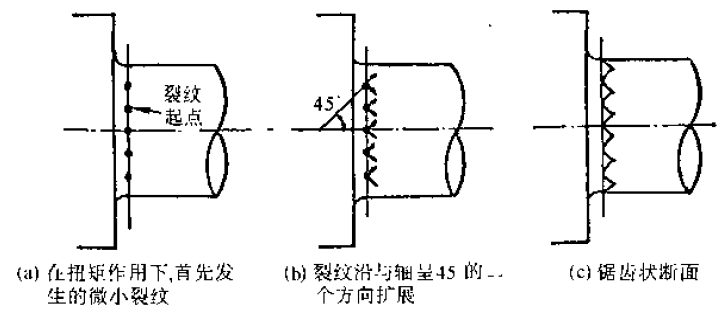
Figure 6-16 Schematic diagram of the formation of zigzag fatigue fracture under the action of two-way torsional load
If an axial notch such as a spline or a keyway is formed in the shaft, stress concentration occurs at the corner of the groove, where the crack is generated and spreads in a direction perpendicular to the maximum tensile stress. Especially for spline shafts, fatigue sources may be formed at each sharp corner, each of which expands in a direction perpendicular to the tensile stress, and finally merges at the center of the shaft to form a star-shaped fracture. The formation process is shown in Figure 6- 17 shows.

Figure 6-17 Schematic diagram of star fracture and formation process
For the torsional fatigue of the cut-off type, the fracture is a flat fracture perpendicular to the axis or stepped. The fatigue expansion zone is smoother, and the fuzzy fatigue curve is visible. The instantaneous break zone is a fiber tear, and there is a spiral pattern along the twist direction. Figure 6-18 shows a cut-off torsional fatigue fracture.

Figure 6-18 Cut-off torsional fatigue fracture
The above describes the typical fatigue fractures in the case of relatively simple stress states. The shape and stress state of the components in engineering practice are much more complicated, and their fatigue fracture under service conditions is much more complicated. But the analysis of these typical fatigue damages is very helpful in studying complex situations.
In addition, there is a damage mode that is fatigue damage, that is, contact fatigue. This is a kind of failure mode formed on the surface of the component under alternating contact stress, such as puncture fatigue peeling of the gear tooth surface, fatigue peeling of the hardened layer, etc., and these surface fatigue damage are all in contact with the tile surface. Relatedly, its main manifestation is pitting cracks and chip erosion on the contact surface. The cyclically acting contact maximizes the periodic shear stress not far below the surface layer, and the cyclic shear stress causes cracking.
The forms of damage associated with fatigue are impact fatigue, corrosion fatigue, creep fatigue, fretting fatigue and thermal fatigue. Its fracture morphology has its own characteristics, it is worth noting. There is no in-depth discussion here.
Other Special Steel Is different from the traditional steel, it is mainly formed by the alloy, generally has good oxidation resistance, corrosion resistance, high temperature resistance and other characteristics, it can be applied in a very harsh environment. Used for special industries. The main use is the production of various furnace components, the maximum temperature of 1300 degrees Celsius, could be applied in the condition of high temperature 1150℃. Such as furnace materials, automotive cleaning equipment, materials, etc.. As well as nuclear reactor cooling system, heating furnace, carburizing basket and fasteners, heat treatment fixture.

Other Special Steel
Alloy C276 Materials,Welding Of Nickel Alloys,Stainless Steel Welding Wire,Monel 400 Properties
Jiangsu nickel alloy Co.,Ltd , https://www.xhalloy.com